Mining Publication: Technology News 540 - Field-Expedient Shotcrete Adhesion Test System
Original creation date: June 2011
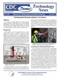
Objective: To develop a practical method of measuring shotcrete adhesion strength in underground mines. A more thorough understanding of the in-situ strength properties of shotcrete, particularly the bond strength of shotcrete to the rock, will lead to improvements in ground support practices, thereby preventing ground falls and reducing mine roof-fall incidents. Background: When shotcrete is used as an integral part of a mine's ground support system, it is important to know the strength properties of the in-place shotcrete. To quantify the bond strength of the shotcrete to the rock, a shotcrete adhesion test system has been developed for use in underground mines. The test system consists of readily available components, primarily a small stand-mounted core drill and a pulling unit equipped with a precision pressure gauge. All of these components are rugged and portable, and they can reliably be used to measure the adhesion strength of shotcrete app lied to the surface of an underground mine opening. With this test method, a direct tensile load is applied to a core drilled through the shotcrete into the underlying rock. As this load is gradually increased, the test core typically breaks or fails in tension. This tensile failure can occur in the shotcrete, at the bond surface (interface), in the rock, or at some combination of these locations. As a result, the tensile-strength values derived from these tests provide important information about the quality of the applied shotcrete and the competency of the underlying rock, as well as the bond strength of the shotcrete to the rock. Conducting the Shotcrete Adhesion Test: Once a desired test site has been selected, a hand-operated rotary percussive drill is used to drill a 16-mm x 51-mm (0.625- in x 2-in) hole for anchoring the drill stand. After installing a 13-mm- (0.5-in-) diameter threaded stud and expansion anchor in this hole, the drill stand is leveled and secured in position. Three holes are then drilled from this drill setup ensuring that all of the holes are parallel and concentric. First, an 11.1-mm- (0.4375-in-) diameter hole is drilled dry into the shotcrete using a rotary percussive bit, to a depth of 60 mm (2.375 in), assuming a shotcrete thickness of 75 mm (3 in). Next, the hole is cleaned, filled with a quick-setting, two-part epoxy adhesive, and a 9.5-mm- (0.375-in-) diameter pull anchor is inserted. After the epoxy has initially set or gelled (about 15 min), a 102-mm- (4-in-) diameter diamond core bit is used to wet drill a second hole through the shotcrete to a depth of about 25 to 50 mm (1 to 2 in) into the underlying rock. Finally, a 127-mm- (5-in-) diameter diamond core bit is used to wet drill a shallow kerf for seating the base of the pulling fixture. After the epoxy has fully set (30-60 min), a threaded extension rod is connected to the pull anchor with a coupling nut; the pulling fixture is then carefully placed over the core sample with the base of its reaction ring positioned in the kerf of the outer drill hole. Next, a collet and a slip-on, quick-threading locknut are connected to the threaded extension rod to serve as a mechanical stop for the pulling fixture's ram. The hydraulic hose from the hand pump is then connected to the loading ram, and the pressure gauge is zeroed. To conduct a test, an increasing tensile load is applied to the core sample through a slow and steady movement of the pump handle until the core breaks. The adhesion strength of the test core is determined by converting the maximum hydraulic pressure value, saved on the pressure gauge's digital display, to the maximum tensile stress acting normal to the core's failure surface. Typical adhesion test results comparing tensile strength with shotcrete curing age are shown in Figure 4.
Authors: JB Seymour, CC Clark, LA Martin
Technology News - June 2011
NIOSHTIC2 Number: 20039246
Pittsburgh, PA: U. S. Department of Health and Human Services, Public Health Service, Centers for Disease Control and Prevention, National Institute for Occupational Safety and Health, DHHS (NIOSH) Publication No. 2011-185, TN 540, 2011 Jun; :1-2
See Also
- Diagnosing and Controlling Moisture-Sensitive Roof in Coal Mines
- Effects of Far-Field Shearing Deformation on Fracturing Around an Underground Opening
- The Introduction of Roof Bolting to U.S. Underground Coal Mines (1948-1960): A Cautionary Tale
- The Long-term Performance of Surface Support Liners for Ground Control in an Underground Limestone Mine
- Optimizing Secondary Roof Support with the NIOSH Support Technology Optimization Program (STOP)
- Origin of Mining-Induced Fractures Through Macroscale Distortion
- Preventing Injuries Caused by Unrecognized Stone Mine Roof Beam Failures With a Pro-Active Roof Control Plan
- Roof and Rib Fall Incident Trends: a 10-Year Profile
- Technique to Assess Hazards in Underground Stone Mines: the Roof Fall Risk Index (RFRI)
- Technology News 542 - Field Use Round Determinate Panel Test System
- Content source: National Institute for Occupational Safety and Health, Mining Program


 ShareCompartir
